
Drilling and wells on Frigg
Production wells for the field were drilled between 1976 and 1979 – 24 each from CDP1 and DP2. Production began from the first of these platforms on 13 September 1977, with DP2 following on 9 September 1978.
Because reservoir permeability through the oil/gas system was so good, all the production wells were located within a five-kilometre radius. Forty-seven of them were used as active producers, while the 48th – 25/1-A22 – was used to observe changes in pressure and the oil-water contact.
After five years of production, more surveys were carried out to map water intrusion. High-resolution three-dimensional seismic surveys were carried out in 1984-85, allowing large volumes of additional geological and geophysical data to be included in an updated reservoir model. This led in turn to three new shallow production wells being drilled down to the aquifer (water-bearing strata).
Two deviated wells – 25/1-A17A and A4A – were drilled in 1989 from DP2. The first of these tapped a structurally high area north of the principal wells. Simulations had shown that recovery could be increased in this way.
The 25/1-A4A well was drilled towards the south. This made it possible to recover residual gas at the top of the geological structure under CDP1 once all the wells from that platform had been shut in.
Production was halted on CDP1 in 1991-92 because of water intrusion in the wells, which reduced flow rates. Such intrusion remained much lower in the area covered by DP2 for a long time.
Plugs were eventually placed in the production tubing/casing of DP2 wells to keep water out. This was done on three wells in 1993, one in 1999, two in 2000 and one in 2001. Wells from DP2 passed through more layers of shale than those in the CDP1 area. The plugs meant that water was effectively excluded from the wells where contact with formation water caused the shale layers to swell.
DP2 was without permanent staffing from September 2005, and remotely operated by the control room on the QP quarters platform. Thirteen wells remained in operation on DP2, three of which were reopened after being shut down for a period.
After 1900, when Frigg had come off plateau and was in decline, efforts were made to keep production under the critical rate for the field. That resulted in satisfactory utilisation of the more distant northern reserves. A total of 17 billion standard cubic metres were produced while the field was in decline, which boosted the recovery factor for the reservoir from 70 to 76 per cent.
The period of declining production proved economically feasible following the implementation of a drastic cost-cutting programme as well as an optimum reservoir management and production strategy.
Twelve wells were available for production in 1997 on DP2. All these had a reduced production potential by that time because of water intrusion. The final well on DP2 was shut down in October 2004, when Frigg ceased to produce.
The drilling programme
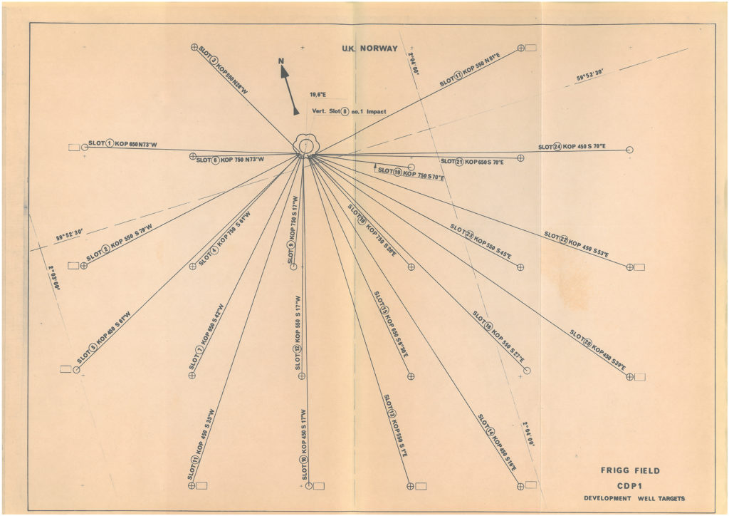
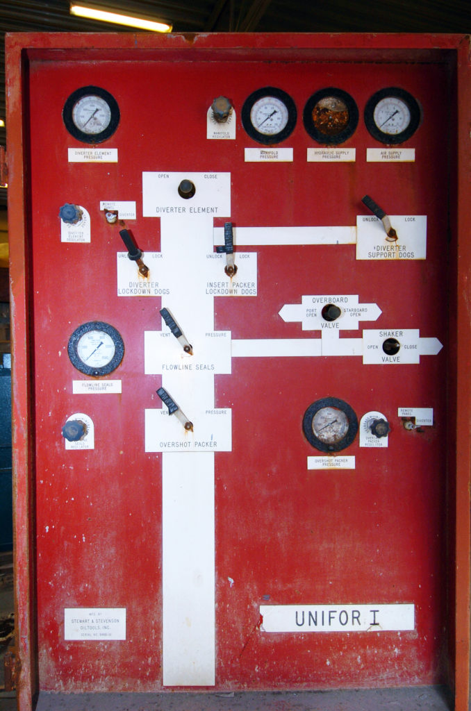
Production drilling on Frigg was carried out from the CDP1 and DP2 platforms, each of which had 24 well slots. Wells on the platforms were divided into two groups of 12 slots – cluster west and cluster east – and separated by a firewall. Drilling equipment on CDP1 was a Saipem Rig Emsco C3 unit, while DP2 had a Unifor 1 rig.
The sketch maps below show the placement of wells from the two platforms.
One vertical and 23 deviated wells were drilled on each platform to a vertical depth of 2 020 metres measured from the drill floor. The oil/gas contact lay about 1 995 metres down.
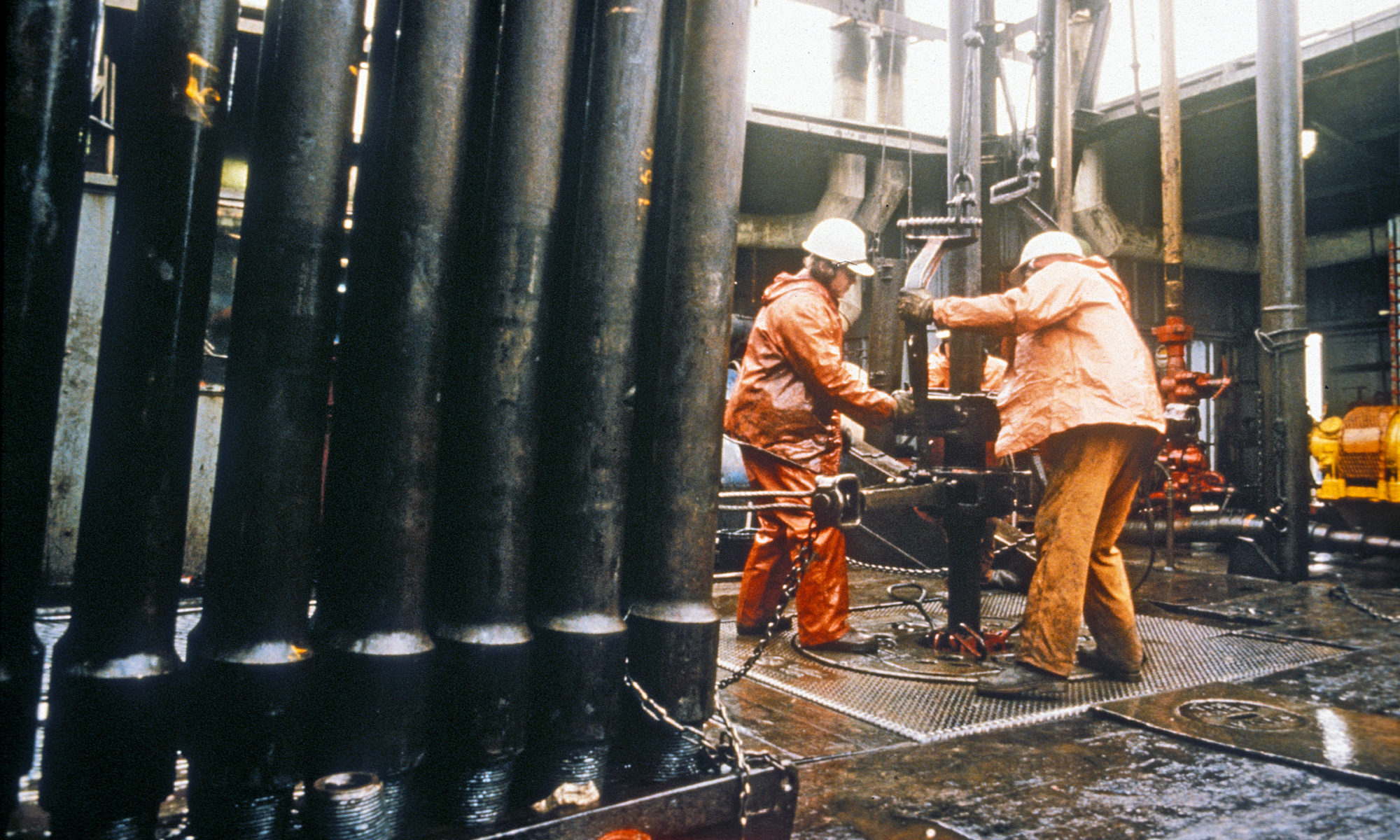
In order to start gas deliveries quickly, production had to begin while drilling was still under way on the platforms. The biggest hazards which could occur were a shallow-gas blowout, a blowout from the formation, and simultaneous production and drilling if a well was drilled into one which was already producing.
Elf accordingly kept two drilling superintendents and a mud engineer on the platforms during drilling operations in order to ensure proper management of the work and to see that the programme was carried out.
Casing
The casing was intended to secure the borehole against changes in formation pressure and to provide a good footing for the blowout preventer (BOP).
The first two casing strings differed between the platforms. On CDP1, a 26-inch string was first driven 40 metres into the seabed. This was followed by drilling a 23-inch hole to 450 metres and cementing an 18 5/8-inch casing firmly into place. The DP2 wells began with a 30-inch surface casing to anchor the BOP, followed by a 20-inch string.
Deviated wells
The deviated wells had a maximum angle of 31 degrees from the vertical. Building up this deviation began when drilling the well with a 17½-inch bore (see the example below). To achieve the desired angle, the bit was diverted with the aid of a downhole motor, and a Sperry Sun gyro was used to measure the deviation and direction of the well path. Cores were taken from the lowest 70 metres of the vertical wells – one per platform.
Drilling safety
Safety precautions included the installation of three casing strings and a production tubing in each well. These were attached to the wellhead and Christmas tree (valve assembly) on the platform.
The well control system comprised three valves in each well – one automatic downhole safety valve 60 metres beneath the seabed, an automatic main valve in the wellhead and a manually-operated main valve on the Christmas tree. During completion work, the two well superintendents were supplemented by two completion superintendents to supervise the work. All completion work was conducted with the same level of caution as the actual drilling. This meant that the blowout preventer (BOP) was kept in place throughout installation work, and the well was filled with mud.
Before removal of the BOP to install the wellhead and Christmas tree, the well was plugged close to its bottom. The mud was then cycled out and the plug removed, leaving the well ready to come on stream.
Blowout preventer
Although deposits of shallow gas were not expected to be present above the Frigg formation, a low-pressure BOP (diverter) was connected as soon as drilling had begun under the surface casing. Once the 13 3/8-inch casing had been set at a depth of 950 metres, the diverter was replaced with a BOP which could withstand the full pressure of 5 000 pounds per square inch (psi).
Distance from neighbouring wells
To avoid drilling into a producing well, all surface casing under the platform was first driven to a depth of 180 metres, followed by the first casing string. The next step was to set the 13 3/8-inch casing string in each 12-well cluster before drilling continued to the reservoir formations which contained the gas.
Completion of well equipment
The Frigg reservoir consisted largely of sandstone with good production properties. Its porosity was 30 per cent, while permeability was measured as 1 Darcy[REMOVE]Fotnote: Permeability is a measure of how easily gas or liquid can flow through a porous rock. A Darcy is the unit of measurement.. The gas cap was 152 metres thick over a 10-metre oil zone.
As soon as production testing of the discovery well (25/1-1) had been completed in 1971, it was clear that completion of the production wells would have to include equipment to prevent sand intrusion.
At that time, no devices were available anywhere in the world to keep rock grains out of wells with such a high rate of production from unconsolidated sand. Elf accordingly launched a major development project which came up with a sand filter design for the Frigg wells.
Production began in September 1977, and inspections of process equipment on the platforms during the following spring showed that no sand was being produced from the wells – even at a flow of 2.2 million cubic metres per day. As a result, the sand traps in the production equipment were removed as early as 1981.